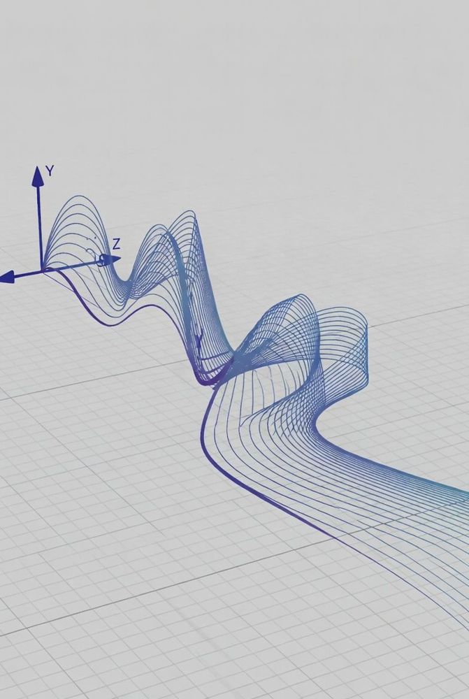
The Challenge of High-Speed Data Links
When designing custom cable assemblies for high-speed video or multi-gigabit data systems—such as HDMI, DisplayPort, USB3, or high-definition camera feeds—engineers often encounter mysterious signal degradation. A prototype cable assembly might pass testing at lower data rates or lower video resolutions without an issue, but as soon as the throughput is increased to 4K or multi-gigabit speeds, display artifacts appear, bit-error rates jump, and the connection drops repeatedly.
Inspecting the output signal from the driver board shows crisp, well-defined digital edges. However, at the receiving end of the raw cable, the differential signal appears smeared and distorted, causing the receiver's eye diagram to close up completely. This performance breakdown is frequently caused by intra-pair skew inside the raw bulk cable.
High-Speed Differential Propagation Mechanics
Modern high-speed serial protocols rely on differential signaling to transfer data reliably over copper lines. Instead of referencing a single wire to a common ground plane, the receiving circuit measures the instantaneous voltage difference between two dedicated conductors: the positive signal line and the negative signal line.
When the transmitter sends a digital pulse, the voltage on the positive line rises while the voltage on the negative line falls at the exact same instant. The differential receiver reconstructs the data waveform by subtracting the negative line voltage from the positive line voltage.
For this system to work reliably, both signal transitions must travel down the cable at identical speeds and reach the receiver at precisely the same moment. The time it takes for a signal to propagate through a conductor depends directly on the physical length of the wire and the dielectric constant of the plastic insulation surrounding it.
Understanding Intra-Pair Skew
Intra-pair skew is the time difference between the arrival of the positive signal and the negative signal at the receiver end of the same pair. This delay gap is driven by two main manufacturing variables in raw cable production.
The first is physical length mismatch. If one conductor in the pair is slightly longer than its partner due to uneven tension or twisting during extrusion, the signal traveling down the longer path takes more time to reach the end.
The second variable is dielectric inconsistency. Microscopic variations in the density or wall thickness of the plastic insulation alter the effective speed of the signal. As a result, even if two wires are cut to the exact same physical length, a signal will travel slightly slower through the wire wrapped in denser insulation.
When intra-pair skew increases in a high-speed link, two main failure modes occur:
- Common-Mode Noise Conversion: When the positive and negative edges become misaligned in time, they no longer cancel each other out. This timing gap transforms part of the differential energy into a common-mode noise pulse, causing high levels of electromagnetic radiation that can easily fail regulatory compliance testing.
- Eye Diagram Closure: In a clean system, the positive and negative signals cross at the exact midpoint of the voltage swing, creating a wide, open timing window (or "eye") for the receiver to distinguish between digital ones and zeros. As skew delays one side of the signal, the crossover point shifts, narrowing the open window. At multi-gigabit speeds where a single data bit lasts only a fraction of a nanosecond, a physical length difference of just one millimeter can introduce enough delay to collapse the timing window entirely, leading to constant bit errors.
Cable Designs that Minimize Skew
Standard off-the-shelf twisted-pair wire is rarely suitable for gigahertz data speeds over extended distances. High-speed systems require bulk cables specifically engineered for low intra-pair skew.
One widespread solution is precision twinaxial cable design. Instead of twisting the two conductors around one another, high-speed twinax routes the positive and negative conductors perfectly parallel inside a continuous foil shield. Because there are no twists, the physical path lengths of both conductors remain identical throughout the cable run.
Another approach is bonded dielectric extrusion. In this design, cable manufacturers co-extrude the insulation for both conductors simultaneously, fusing them into a parallel ribbon profile before applying the outer shield. This process locks in uniform center-to-center conductor spacing and identical insulation density.
When specifying bulk cable for high-speed differential signals, check the manufacturer's datasheet for explicit skew limits. High-performance video and data cables clearly specify maximum allowable skew—often rated in picoseconds per meter—ensuring timing alignment remains intact over the entire cable run.