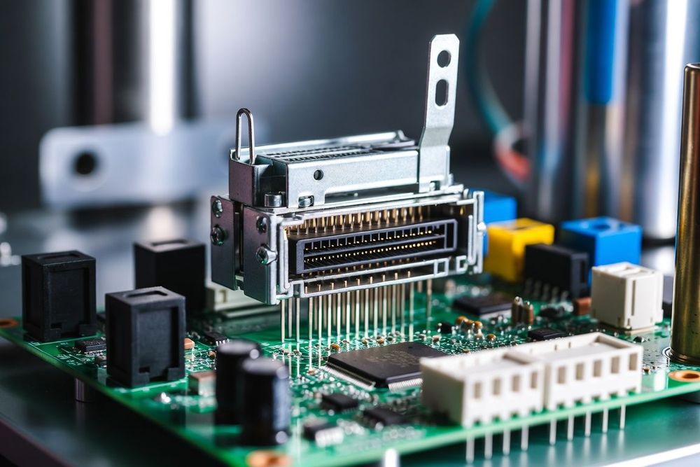
Flexible Printed Circuit (FPC) and Flat Flexible Cable (FFC) connectors are essential components for interconnecting displays, touch panels, sensor arrays, and sub-assemblies in compact electronic systems. When selecting an FPC connector, hardware engineers generally choose between two primary mechanical architecture options: Zero Insertion Force (ZIF) connectors and Non-Zero Insertion Force (Non-ZIF) connectors.
While ZIF connectors rely on a movable mechanical actuator or flip-lock slider to clamp the flexible circuit onto the internal electrical contacts, Non-ZIF connectors feature no moving parts. Instead, they rely purely on engineered contact friction and spring deflection to achieve connection stability and electrical continuity.
Related reading: for a detailed side-by-side comparison between these two connector families, see our companion guide, ZIF vs. Non-ZIF FPC/FFC Connectors. For insights into actuator durability, see ZIF/Non-ZIF FPC Connector Latch Failure Prevention.
The Mechanics of Non-ZIF Retention
The defining characteristic of a Non-ZIF connector is its simplified single-piece housing structure. The mechanical retention and electrical connection are performed simultaneously during the physical insertion of the flexible circuit into the connector throat.
Non-ZIF Insertion Mechanism:

Flex Circuit Inserted -> Deflects Internal Cantilever Beams -> High Normal Force Applied -> Friction Locks Cable
1. Spring Contact Deflection and Normal Force
Inside a Non-ZIF connector housing, the internal metallic contacts are pre-formed cantilever beams extending into the insertion path. The entry slot width is engineered to be narrower than the combined thickness of the FPC substrate, copper conductors, and stiffener plate.
When the technician inserts the FPC tail into the connector, the lead edge of the flex circuit forces the spring contact beams upward (or outward), and the spring contacts resist this displacement, applying a continuous, pre-loaded normal force directly onto the exposed gold or tin plating of the FPC contact fingers.
2. Friction-Driven Retention Mechanics
Because there is no actuator arm to lock the cable in place, the retaining force holding the FPC inside the housing is entirely governed by the friction relationship: retention force equals the coefficient of static friction (µ) multiplied by the total normal force applied across all contact beams (F_retention = µ × N_total).
To supplement this friction, many modern Non-ZIF connectors feature specialized "top-contact" or "bottom-contact" barb geometries or side ear-hooks. These elements engage matching notches cut into the sides of the FPC stiffener, creating a mechanical detent that increases the pull-out force without requiring a separate latch.
The Insertion Force Trade-Off
The primary trade-off of the Non-ZIF architecture is the relationship between insertion force and retention force. Because the flex circuit must mechanically overcome and deflect the pre-loaded spring contacts during insertion, the force required to seat a Non-ZIF cable is significantly higher than that of a ZIF connector (which offers near-zero resistance when the latch is open).
High Contact Normal Force  ->  Stronger Cable Retention (Good)
                           ->  Higher Cable Insertion Force (Assembly Resistance)
If an FPC design features a high pin count (e.g., over 30 to 40 contacts), the cumulative insertion force can become high enough to buckle thin flex cables during assembly. Consequently, Non-ZIF connectors are typically restricted to lower contact counts, frequently 2 to 20 pins.
When Non-ZIF is the Superior Engineering Choice
Despite the higher insertion resistance, Non-ZIF connectors offer compelling mechanical and economic advantages in specific production scenarios:
- Cost-Sensitive, High-Volume Consumer Products: With zero moving parts, Non-ZIF connectors are simpler to mold, stamp, and assemble. This translates to lower unit costs compared to complex multi-part ZIF assemblies. In high-volume products like smart meters, basic appliances, or budget peripherals, these per-unit savings scale significantly.
- High-Vibration / Shock Environments: Flip-lock actuators on ZIF connectors can accidentally release or fracture under severe operational shock or continuous vibration if not backed by heavy secondary tapes. A Non-ZIF connector's solid-state housing cannot "pop open" under mechanical stress.
- Extremely Low Z-Height Profile Constraints: Omitting the top-opening flip-latch allows Non-ZIF connectors to achieve low profile heights (often under 0.9mm total profile), making them ideal for thin enclosures.
- Simplified Automated / Manual Assembly: Assembly operators can insert the flex cable in a single fluid motion, omitting the secondary "flip closed" step required by ZIF latches.
Failure Modes Specific to Non-ZIF Designs
Engineers specifying Non-ZIF connectors must design around failure modes unique to friction-fit flex systems:
- Contact Wear from Repeated Mating Cycles: Each insertion slides the FPC pads directly against the pre-loaded metal contacts under high normal force. This rubbing action causes mechanical wear on thin contact plating. Non-ZIF connectors typically support only 5 to 20 mating cycles before plating degradation risks exposing base metal to oxidation.
- Flex Cable Buckling or Delamination: If the FPC stiffener is too thin or flexible, the operator may buckle the flex tail during insertion. Additionally, poor adhesive bonding between the stiffener plate and the polyimide layer can cause delamination under high insertion forces.
- Fretting Corrosion from Micro-Motion: In high-temperature or high-vibration applications, small relative thermal expansion movements between the FPC pads and the spring contacts can cause fretting wear, generating non-conductive oxide debris that leads to intermittent open circuits.
Always verify the manufacturer's maximum recommended insertion/withdrawal forces and recommended FPC stiffener thickness tolerance (typically 0.30mm ± 0.03mm). Specifying an FPC with an incorrect stiffener thickness will directly compromise contact retention force or make insertion impossible.