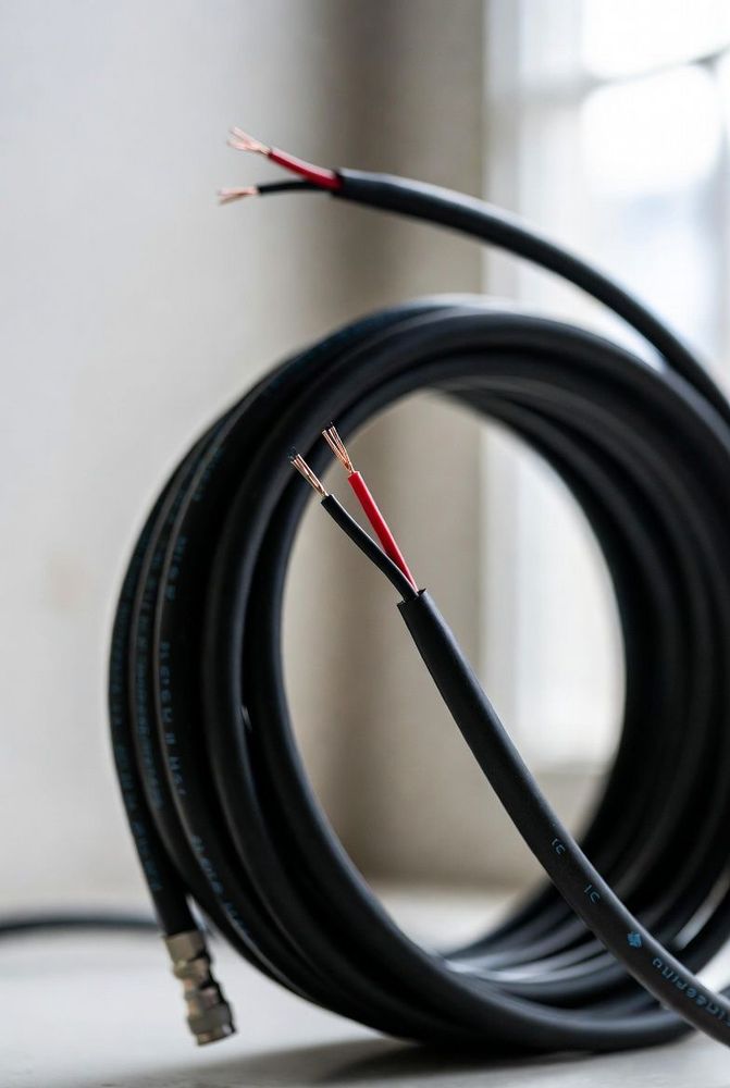
Non-Electrical Components in Cable Design
Stripping open a multi-conductor industrial cable reveals a variety of non-conductive materials alongside the insulated copper wires: soft cotton threads, rigid plastic cross-shaped dividers, thin clear polyester tapes, or tissue paper wraps.
Engineers new to cable specification sometimes wonder if these non-electrical elements are necessary, or if removing them could make cables thinner and cheaper. However, omitting these structural materials leads to distinct real-world failure modes: cables lose their round shape, develop flat spots, pinch and short under tight bends, or suffer damaged insulation during jacket stripping.
Maintaining Roundness and Extrusion Uniformity
When three, four, or more round insulated conductors are bundled together, empty gaps naturally form between the wires.
If an outer plastic jacket is extruded directly over an un-filled wire bundle, the hot, molten plastic sags into these empty spaces under extrusion pressure. This creates an irregular, oval cable with thin, uneven jacket walls that wear through quickly when exposed to abrasion.
To prevent this, non-conductive filler materials—such as polypropylene rods or soft cotton yarns—are laid into these gaps alongside the insulated conductors during the bundling process. Packing these voids creates a round, uniform core profile, allowing the jacket extruder to apply a consistent wall thickness around the full circumference of the cable.
Signal Isolation with Cross-Web Splines
In high-performance networking cables like Category 6 and Category 6A, a continuous star-shaped plastic rod—known as a cross-web spline—runs down the center of the core.
The primary function of the spline is physical pair separation. It divides the four twisted pairs into separate isolated quadrants throughout the entire length of the cable.
Because high-frequency capacitive crosstalk drops off rapidly with distance, keeping adjacent pairs separated by even a single millimeter reduces near-end crosstalk significantly. This physical spacing is a primary reason Category 6 cables handle much higher bandwidths than older Category 5e designs.
Thermal Barriers and Manufacturing Protection
During cable manufacturing, molten jacket plastic—often heated above 180 degrees Celsius—is extruded around the internal wire bundle under high pressure.
Without a protective barrier, this intense heat would cause the outer jacket to melt and fuse directly to the thin insulation of the inner conductors. To prevent this, manufacturers wrap the inner bundle with thin tissue paper, PTFE tape, or polyester film before it enters the extrusion head.
This layer acts as a heat shield, preserving the integrity of the conductor insulation. It also ensures the outer jacket strips away cleanly during assembly without tearing or pulling the underlying wire insulation.
Strain Relief and Mechanical Durability
In high-flex applications, robotics, and handheld devices, non-conductive internal materials also provide critical mechanical reinforcement:
- High-tensile aramid fibers, such as Kevlar, or heavy cotton cords are often placed at the center of the cable core. When the cable is pulled during installation or operation, these strength members absorb the tensile force, protecting the delicate copper strands from stretching or breaking.
- Smooth wraps like tissue paper or PTFE tape reduce internal friction. As a cable bends repeatedly in a dynamic machine, these low-friction barriers allow adjacent conductors to slide past one another smoothly, preventing internal binding and wire fatigue.
When terminating cables, handle these internal materials properly. Use sharp flush cutters to trim fillers, splines, and strength fibers level with the jacket edge so they do not interfere with connector backshells or strain-relief boots.